A Copper Electrode 25kW Hollow Cathode Reverse Polarity Thermal Air Plasma Torch (CERPPT- 25kW) along with the Plasma Power Source is available for transfer of technology for industrial as well as R&D application. It uses air / nitrogen as plasma gas and generates a 300-400mm long jet of high thermal energy density. The torch has more than 150hr of electrode life. The torch is rugged and is able to operate for long duration. The torch has advanced double cup design and it operates in reverse polarity, i.e. the plume side electrode is cathode. This leads to higher thermal efficiency, longer plume length and higher temperature in the plume. This torch has user friendly design with ease of fabrication, assembly, installation and operation. The technology also includes complete design of a plasma power source with all necessary features. The combined system provides a robust and complete package for thermal plasma applications.
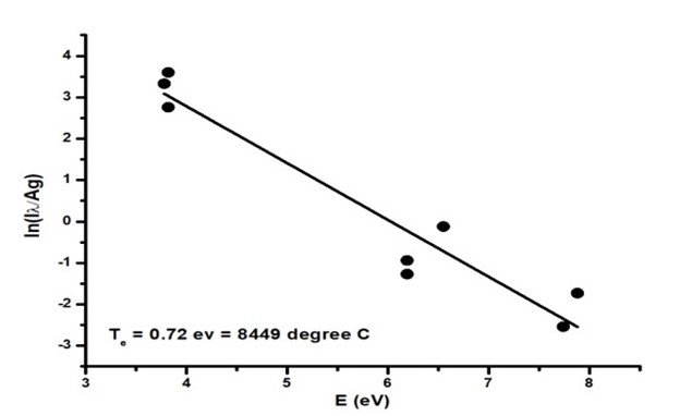
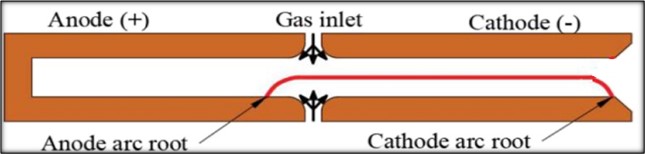
This 25kW power air thermal plasma torch is very important for high temperature industrial processes like incineration, pyrolysis, melting, cutting, welding, spraying, and waste treatment. Their ability to generate long plume of high density plasma having temperature >6000K enables a diverse wide range of applications in nuclear and other industries. The torch has been designed, simulated and tested using multiphysics and CAD software to obtain optimum performance including operating power, voltage, current, arc attachment location and thermal efficiency. The efficiency of torch is very high ~70%. The torch has modular design enabling, replacement of a small consumable part over the long life of the torch. Fig. 1 describes schematic of CERPPT-25kW.
This torch is energised by a custom built plasma power source. The power source is 45 kW, 150A DC suitable for Thermal Plasma torch consists of a main arc DC power supply and a trigger unit. The trigger unit initiates arc and main arc power supply gives energy to maintain it. The main arc power supply have fast response to enable stabilizing the plasma. The main arc power source is based on 25 kHz IGBT inverter operating in constant current mode. 3kV, 3 MHz trigger unit is based on capacitor discharge through spark gap. Trigger unit is inductively coupled with main arc power supply.
A high voltage high frequency (HVHF) supply is required for initiation of the discharge between the cathode and anode having a designed gap. Since the electrical resistance of the gas in the plasma torch is high the open circuit voltage of the main arc power supply cannot cause a breakdown in the inter electrode gap. A trigger unit having HV 3-5 kV @3 MHz can easily produce breakdown between the electrodes. This trigger produces initial ionization of the gas which lead to plasma in the inter-electrode gap. Once the plasma discharge is initiated, its low electrical resistance enables the main arc power supply to take over and maintain the plasma discharge.
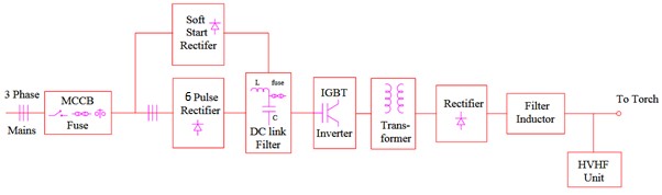
The block diagram of a typical power source for thermal plasma application is given in Fig. 2 below. The major blocks of this power source are front end rectifier & DC link filter, Soft start rectifier, IGBT inverter, High frequency link transformer output rectifier & filter and HVHF unit.
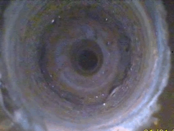
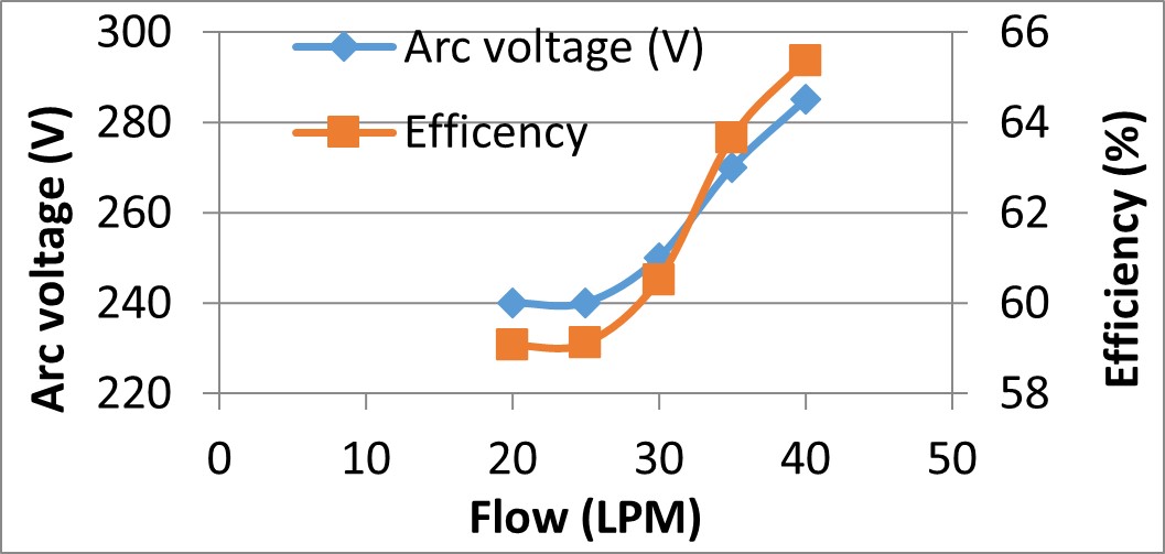
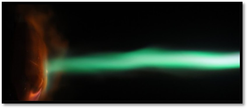
A Copper Electrode 25kW Hollow Cathode Reverse Polarity Thermal Air Plasma Torch (CERPPT- 25kW) has been designed and developed for industrial as well as R&D application. This plasma torch uses air / nitrogen as plasma gas. The plume has high thermal enthalpy (7-8 MJ/kg). The torch has more than 150hr of electrode life. The torch is rugged and is able to operate for long duration. It has advanced double cup design and operates in reverse polarity, i.e. the plume side electrode is cathode. This leads to higher thermal efficiency (~70%), longer plume length (300-400mm long) and higher temperature (~8500C) in the plume. This torch has user friendly design with ease of fabrication, assembly, installation and operation. The technology also includes complete design of a plasma power source with all necessary features. The combined system provides a robust and complete package for thermal plasma applications. The torch produces plasma plume as intense and luminous atmospheric pressure broom shaped plasma. The plume dimensions and power content can be tailored by suitably adjusting operating parameters e.g. air flow and arc current.
The power source of 25 kW, 150A DC for Thermal Plasma torch consists of a main arc DC power supply and a trigger unit. The trigger unit initiates arc and main arc power supply gives energy to maintain it. The main arc power supply have fast response to enable stabilizing the plasma. The main arc power source is based on 25 kHz IGBT inverter operating in constant current mode. 3kV, 3 MHz trigger unit is based on capacitor discharge through spark gap. Trigger unit is inductively coupled with main arc power supply.
A Copper Electrode 25kW Hollow Cathode Reverse Polarity Thermal Air Plasma Torch (CERPPT- 25kW) along with the Plasma Power Source is available for transfer of technology for industrial as well as R&D application. It uses air / nitrogen as plasma gas and generates a 300-400mm long jet of high thermal energy density. The torch has more than 150hr of electrode life. The torch is rugged and is able to operate for long duration. The torch has advanced double cup design and it operates in reverse polarity, i.e. the plume side electrode is cathode. This leads to higher thermal efficiency, longer plume length and higher temperature in the plume. This torch has user friendly design with ease of fabrication, assembly, installation and operation. The technology also includes complete design of a plasma power source with all necessary features. The combined system provides a robust and complete package for thermal plasma applications.
This 25kW power air thermal plasma torch is very important for high temperature industrial processes like incineration, pyrolysis, melting, cutting, welding, spraying, and waste treatment. Their ability to generate long plume of high density plasma having temperature >6000K enables a diverse wide range of applications in nuclear and other industries. The torch has been designed, simulated and tested using multiphysics and CAD software to obtain optimum performance including operating power, voltage, current, arc attachment location and thermal efficiency. The efficiency of torch is very high ~70%. The torch has modular design enabling, replacement of a small consumable part over the long life of the torch.
This torch is energised by a custom built plasma power source. The power source is 45 kW, 150A DC suitable for Thermal Plasma torch consists of a main arc DC power supply and a trigger unit. The trigger unit initiates arc and main arc power supply gives energy to maintain it. The main arc power supply have fast response to enable stabilizing the plasma. The main arc power source is based on 25 kHz IGBT inverter operating in constant current mode. 3kV, 3 MHz trigger unit is based on capacitor discharge through spark gap. Trigger unit is inductively coupled with main arc power supply.
A high voltage high frequency (HVHF) supply is required for initiation of the discharge between the cathode and anode having a designed gap. Since the electrical resistance of the gas in the plasma torch is high the open circuit voltage of the main arc power supply cannot cause a breakdown in the inter electrode gap. A trigger unit having HV 3-5 kV @3 MHz can easily produce breakdown between the electrodes. This trigger produces initial ionization of the gas which lead to plasma in the inter-electrode gap. Once the plasma discharge is initiated, its low electrical resistance enables the main arc power supply to take over and maintain the plasma discharge.
The block diagram of a typical power source for thermal plasma application is given in below. The major blocks of this power source are front end rectifier & DC link filter, Soft start rectifier, IGBT inverter, High frequency link transformer output rectifier & filter and HVHF unit.
SPECIFICATIONS OF THE SYSTEM
| Sr. No. | Parameters | Specifications for indented items |
|---|---|---|
| 1. | Input Voltage | 415 V ± 10%, 3Ph, 50Hz± 3%, 4 WIRE SYSTEM |
| 2. | Input kVA Max. MAX. | 75 kVA at 80% efficiency |
| 3. | Class of Insulation | Class H |
| 4. | Power Factor | > 0.9 |
| 5. | System Frequency | 25 kHz or Higher |
| 6. | Mode of Control | Constant Current Control (PWM Control) |
| 7. | Open Circuit Voltage | ≥ 600 V ± 10% |
| 8. | Max Output voltage | ≥ 300 V (at full load) |
| 9. | Max Output Current | 150 A |
| 10. | Max output Power | 150 A/300 V DC Power will be limited to 45 kW |
| 11. | Cooling | Forced Air Cooling |
| 12. | Input Current THD | as per latest IEEE std 519 |
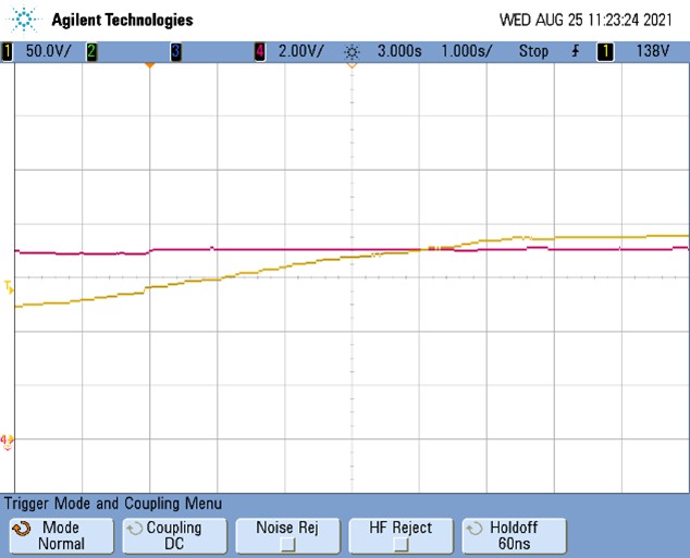
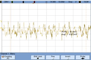
| 13. | Output Current Ripple % | ≤ 1% at full load |
| 14. | HF Unit | 3MHz, > 3 kV (RMS), Power: 100W±5% with Built-in protection circuit |
| 15. | Current Feedback System | Hall effect sensor with accuracy 1% |
| 16. | Output current filter | Third order inductive filters |
| 17. | Max. Ambient operating condition | temperature : 45 Deg. C Humidity : 87% at 45 C |
| 18. | IP RATING | Minimum IP31 rated panel should be used |
| 19. | 3 phase input interlocks (Restricts user to switch ON mains contactor) | Door open, Input under voltage, Input over voltage, Input Phase Fail, Input phase rever-sal, apart from the digital interlocks Fast Fuses of sufficient rating should be provided. |
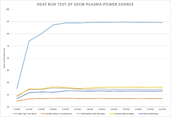
| 20. | Protection interlocks (re-moves the PWM pulses to IGBT and allows only after removal of faults) | Output Overcurrent (> 110% for more than 1 seconds), output overvoltage (>120% of open circuit voltage, should be adjustable) and IGBT over temperature (>60 °C at heatsink, Dsat sensing in driver), Fast rectifier heatsink over temperature (>60 °C), Trans-former over temperature (> 80 °C), Surge protection device |
| 21. | Communication port | Ethernet port |
| 22. | Measurement display on front panel | Voltage, Current, Power |
| 23. | Input cables along with cable trays | 3.5 Core, > 70 sq. mm. flexible copper cable or
3.5 Core > 100 sq. mm. flexible aluminum cable Length : 10 to 25 m depending on installation requirement |
| 24. | Output cables | > 70 sq. mm. copper flexible wire or > 120 sq. mm. aluminum flexible wire |
| 25. | Communication cable | CAT 6 STP cable, length: 100 m |
| 26. | Wheels | 4 Nos. of caster wheels at bottom should be provided of sufficient weight capacity with facility for wheels locking. |
| 27. | Argon & Air digital MFC RANGE |
Air : 0 – 300 LPM
Argon : 0- 50 LPM |
| 28. | Controller type | PLC |
Testing of technology
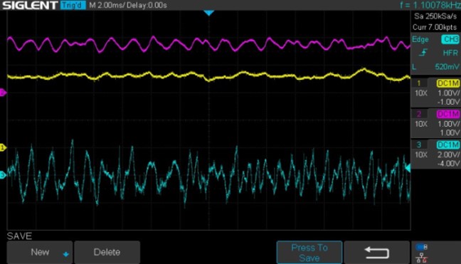
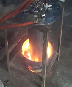
The technology has undergone rigorous testing. A protocol / SOP has been developed for assembly and testing for both CERPPT-25kW torch and power source. The Table 1 shows various photographs of testing of power source and plasma torch.
| Routine test | Type test |
|---|---|
|
|
| Routine test | Type test |
|---|---|
|
|
RAW MATERIALS
The raw material required are electrical components like copper rod, Teflon rod, Fasteners, O-ring, fittings, SS plates for holding structures, SS rod/pipe
EQUIPMENTS
Lathe machine, Milling machine, Brazing setup, Air compressor, Hydro test setup, Trigger power source, Argon gas supply, Welding machine and cooling water, Electrical test and measurement equipment such as Multimeter, Clamp on meters, Oscilloscope, Megger etc
SPACE
Floor space of 300 sq. ft. (15ft x 20ft) is required for integration and testing
POWER
3 phase electrical power of suitable rating, Compressed air
MANPOWER
One fitter, one turner/miller, one electrician and one helper is required for assembly/connection & testing of the plasma torch. One electrical engineer with bachelor’s degree, one electrician/wireman and one helper is required for wiring and assembly of the power source.